close
Choose Your Site
Global
Social Media
Author: Site Editor Publish Time: 2026-07-31 Origin: Site
Engineers face a common reality when designing industrial fluid management systems. While a solid-state sensor offers highly reliable measurement for liquids and bulk solids, its accuracy heavily depends on precise application matching. You cannot simply install a generic probe and expect flawless data collection. Every medium behaves differently under various environmental conditions.
Selecting the wrong probe type inevitably leads to false triggers. Ignoring environmental variables causes material buildup errors and unexpected signal loss. These oversights create severe business problems, including costly system downtime and ruined production batches. Maintenance teams often spend hours troubleshooting issues caused entirely by poor initial specification.
This guide provides engineers and procurement teams an evidence-based framework for specifying exact parameters. We will explore how to compare vendor capabilities and execute flawless installations from day one. You will learn the core engineering principles required to integrate this technology successfully into your facility.
The dielectric constant (dK) of the target medium dictates the necessary sensitivity and probe design of the sensor.
Proper grounding and strategic tank placement are non-negotiable for avoiding parasitic capacitance and false readings.
Evaluating a capacitive level sensor manufacturer goes beyond component cost; it requires assessing their custom calibration capabilities, material certifications, and application-specific support.
Standardization on the right sensor reduces maintenance cycles in highly viscous or scaling fluid applications.
You must establish a strict baseline requirement for continuous or point-level measurement. Modern facilities demand reliability without moving parts. Mechanical floats degrade over time. Physical wear leads to eventual component failure. Solid-state devices eliminate this mechanical degradation completely. You need sensors capable of delivering repeatable data across long operational cycles. Success means achieving stable inventory monitoring without scheduling weekly maintenance interventions.
Facility managers often weigh multiple sensor technologies before finalizing a design. Ultrasonic sensors bounce sound waves off the material surface. However, heavy vapors or surface foam easily scatter these acoustic signals. Radar offers exceptional accuracy. Yet, radar units often carry prohibitive costs for simple point-level applications. Mechanical floats provide cheap solutions but jam frequently when exposed to sticky substances.
A properly calibrated Capacitive Level Sensor excels in high-pressure environments. It handles extreme temperatures easily. It resists corrosive chemicals effectively where physical floats dissolve. The technology works beautifully provided the electrical properties of the medium remain stable. You gain tremendous durability by removing internal moving mechanisms.
No technology works perfectly everywhere. You must highlight common limitations early in the design phase. Capacitive measurement relies on consistent electrical properties. Mediums experiencing highly variable moisture content challenge this consistency. For example, grain silos absorbing massive ambient humidity will show shifting readings.
Environments prone to rapid temperature shifts also alter dielectric properties. A liquid heating from 20°C to 90°C changes its capacitive footprint. Engineers must map these thermal variations during the specification phase. If the medium changes composition frequently, you might require advanced auto-calibrating electronics to maintain accuracy.
The dielectric constant forms the absolute foundation of capacitive sensing. We often abbreviate this value as dK or εr. The base dK determines the maximum sensing distance. It also dictates the required amplifier sensitivity. Think of the sensor as one side of a capacitor. The tank wall acts as the other side. The fluid acts as the insulating material between them. A higher dK value creates a stronger electrical signal.
You must apply different selection logic for low dielectric fluids versus high dielectric fluids. Oils, hydrocarbons, and dry plastics typically feature low dK values (usually between 1.5 and 3.0). These materials require highly sensitive probe amplifiers to detect subtle capacitance shifts. Conversely, high dielectric fluids like water or aqueous solutions boast dK values around 80. These liquids generate massive signal changes, making detection incredibly straightforward.
Reference Guide for Industrial Fluid Properties
Fluid Category | Example Medium | Approximate dK Value | Sensitivity Required |
|---|---|---|---|
Low Dielectric | Mineral Oil / Diesel | 1.8 - 2.5 | Very High |
Moderate Dielectric | Alcohols / Glycols | 10 - 25 | Medium |
High Dielectric | Purified Water | 80 | Low (Standard) |
Solid Particulates | Dry Flour / Cement | 2.0 - 3.0 | Very High |
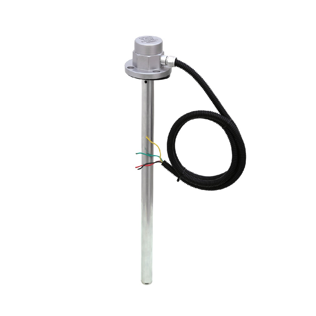
Physical tank dimensions dictate your probe design. You must break down the choice between rigid rods, flexible cables, and flush-mount styles. Rod probes work best in small to medium tanks. They resist bending under moderate fluid movement. Cable probes drop perfectly into towering silos. They span long distances without requiring expensive shipping crates. Flush-mount probes sit flat against the inner vessel wall. You use them when heavy mechanical agitators sweep close to the tank edges.
Wetted materials require strict scrutiny. The probe coating must survive chemical attacks. Specify PTFE or PEEK coatings for highly aggressive acids and strong bases. These plastics resist molecular breakdown exceptionally well. Standard 316L Stainless Steel handles basic aqueous solutions. Food and beverage applications demand polished 316L combined with FDA-approved plastics to maintain hygienic compliance.
Industrial processes routinely push equipment past normal limits. High-heat applications demand special attention. Standard electronics fail rapidly above 80°C. You must outline the necessity for thermal stand-offs in these zones. A stand-off acts as a cooling neck. It physically separates the sensitive circuit board from the hot process connection. Some extreme vessels require completely remote electronics mounted meters away.
Process pressure directly dictates the mechanical seal design. High-pressure steam or compressed gases exploit weak threads. You must match the sensor thread or flange strictly to vessel design codes. High-pressure seals often utilize robust ceramic insulators instead of standard plastics. Always calculate maximum potential spike pressure, not just everyday operating pressure.
False triggers represent the most frustrating challenge in fluid monitoring. Viscous, sticky, or scaling liquids leave thick residues on internal components. A standard probe cannot differentiate between a full tank and a thick coating of syrup. You must specify sensors featuring "Active Shield" or active compensation technology. This technology adds a secondary oscillating circuit near the process connection. The shield signal ignores the localized coating and forces the main sensing field deeper into the tank.
Mounting orientation dramatically impacts physical buildup. You should establish clear guidelines for maintenance teams.
Prioritize Vertical Mounting: Gravity naturally pulls sticky fluids off a vertically hanging rod. This minimizes accumulated volume on the sensing tip.
Angle Horizontal Mounts: If you must mount through a side wall, angle the probe slightly downward. A 10-degree tilt allows condensation and sludge to drip off the tip.
Avoid Recessed Nozzles: Never bury the active sensing zone inside a long metal pipe stub. Material gets trapped inside the nozzle, guaranteeing false positives.
Electrical stability determines data accuracy. You must understand the critical difference between metallic and non-metallic tanks. Metallic tanks inherently provide a massive, stable ground reference. You simply thread the sensor into the metal roof. The tank itself completes the capacitive circuit.
Plastic or fiberglass vessels lack this conductivity. You cannot install a bare probe into a plastic tank and expect reliable readings. The sensor cannot find a proper ground path. You must install a reference ground tube alongside the measuring element. Alternatively, you can apply external metallic grounding plates to the outside of the plastic wall. These additions create the artificial electrical reference required for the circuit to function.
Strategic placement prevents unpredictable signal noise. The electromagnetic field radiates outward from the probe tip. If this field touches internal tank structures unexpectedly, parasitic capacitance spikes. You must provide strict rules of thumb for spatial minimums.
Keep probes at least 300mm away from parallel metallic tank walls.
Maintain maximum clearance from rotating agitator blades to avoid rhythmic signal pulses.
Never install the probe directly beneath an inflow pipe. Falling liquid streams create artificial columns of fluid.
Avoid mounting near heating coils, as localized boiling creates erratic vapor pockets.
Buying complex instrumentation requires strong technical partnerships. You must assess a vendor's ability to provide factory-configured equipment. A competent Capacitive Level Sensor manufacturer delivers pre-calibrated sensors tuned for your specific dielectric ranges. This pre-work saves hours of commissioning time on the factory floor.
Modern applications also demand field-adjustable smart sensors. Look for architectures supporting IO-Link or 4-20mA signals layered with HART protocols. These digital communication standards allow technicians to adjust sensitivity thresholds remotely. You can monitor sensor health diagnostics from the control room rather than climbing tall silos in hazardous weather.
Do not accept vague promises regarding safety. You must require transparent documentation for all industrial certifications. Explosive dust or gas environments legally mandate specific approvals. Demand verifiable ATEX or IECEx certificates before installing equipment in these hazardous zones.
Sanitary applications present similar strict requirements. Dairy processing or pharmaceutical manufacturing cannot tolerate bacterial growth. Request 3-A Sanitary Standards certificates or EHEDG compliance documents. True industrial manufacturers post these certificates openly on their portals. They use independent third-party laboratories to validate their hygienic designs.
You must look far beyond the initial unit price when selecting an instrumentation partner. Evaluate their standard lead times carefully. A cheap component loses its value if you wait twelve weeks for delivery while a production line sits idle. Consider the manufacturer's warranty terms and failure analysis policies.
Furthermore, assess the availability of local technical support. Commissioning advanced digital sensors sometimes requires troubleshooting. Having an expert available for a quick phone call prevents minor setup errors from escalating into week-long delays. Choose partners who maintain robust regional distribution networks and accessible field engineering teams.
Successful deployment of fluid monitoring systems requires a delicate balance. You must align physical sensor specifications perfectly with rigorous installation geometry. Ignoring either side of this equation results in unreliable data and excessive maintenance calls. A well-specified probe, shielded from parasitic noise and properly grounded, operates flawlessly for years.
We advise readers to compile comprehensive medium data before speaking to vendors. Document your fluid's dielectric constant, maximum temperatures, and peak pressure spikes. Sketch out your tank schematics, noting agitators, inflow pipes, and wall materials. This preparation allows vendors to recommend precise solutions immediately.
Take action today by reviewing your most problematic measurement points. Contact an application engineer to review your existing system specifications. Request a prototype of the recommended sensor configuration. Testing a properly tuned probe in your actual process environment will prove the true value of capacitive technology.
A: Yes, it can measure dual interfaces successfully. This works if the dielectric constants of the two liquids differ significantly. For example, oil has a very low dK, while water has a very high dK. The sensor detects the sharp electrical transition between them. However, it requires specialized factory calibration.
A: Condensation heavily impacts standard probes. Thin layers of moisture gathering on the sensing tip often cause false switching. The sensor reads the water droplet as a full tank. You must specify sensors equipped with active shielding or active compensation electronics to ignore these thin layers of moisture entirely.
A: Yes, they monitor viscous liquids effectively. You must select the correct flush-mount design or a smooth PTFE-coated probe. These physical features naturally resist physical adhesion. Combine this non-stick design with proper electronic sensitivity adjustments, and the sensor will reliably track sticky syrups or thick sludges.